The Waldorf-User Frequently Asked Questions
The Inside of a Waldorf Pulse (Rev. 3.3)
Backside of the Waldorf Pulse PCB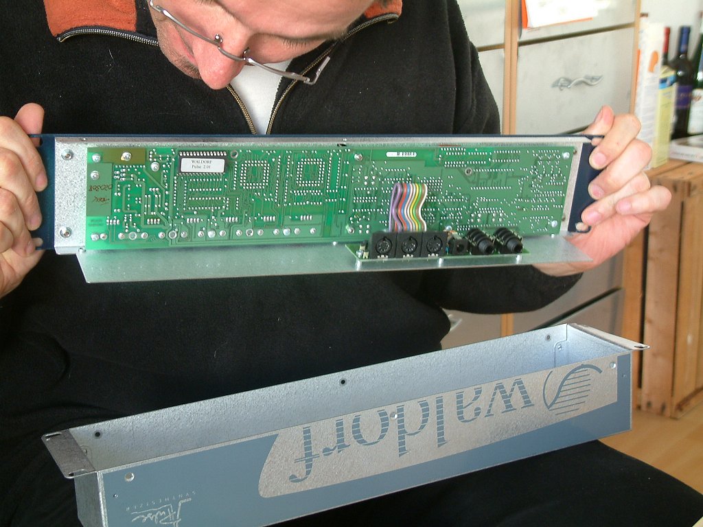
The only item on the backside of the PCB of the Pulse main board is the socked EPROM with the OS. I think I was very clever to put the EPROM here, because it takes only 6 screws to undo to get there. And this is something most people are able to do themself.
Waldorf Pulse PCB
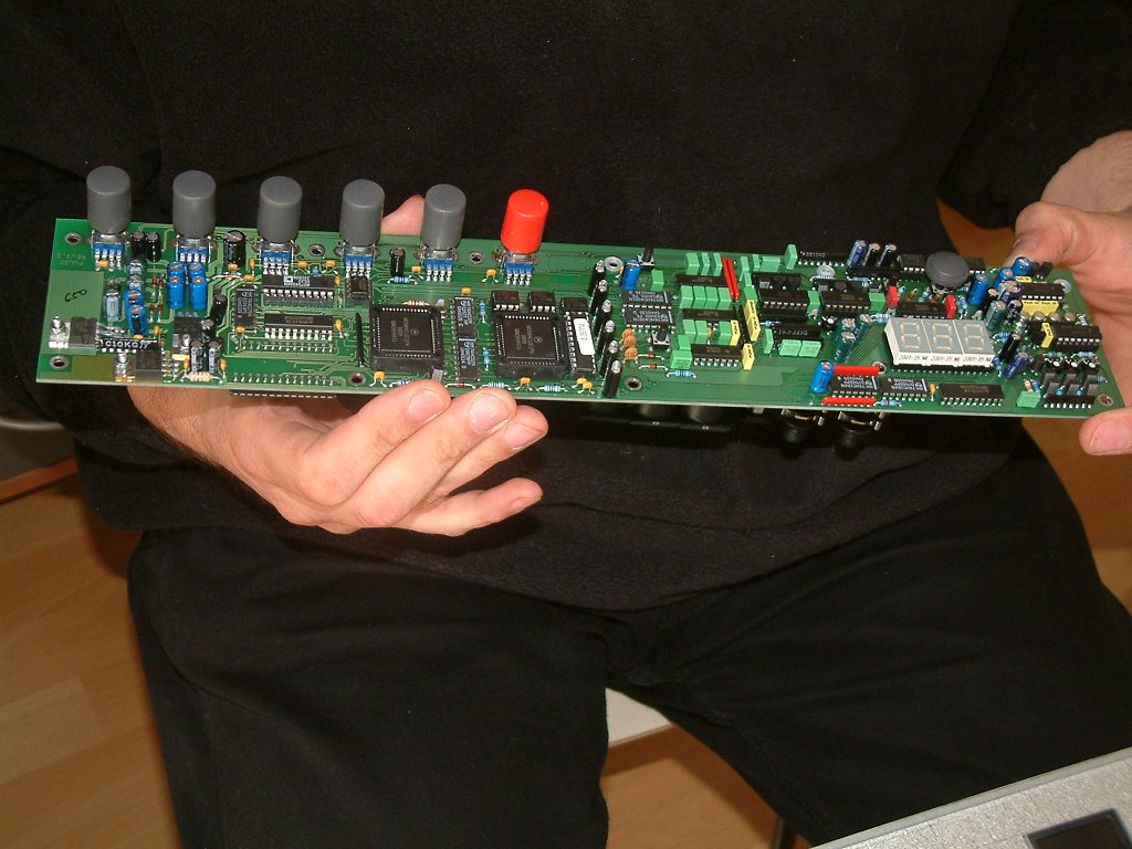
Here is the whole Pulse electronics (except the all the sockets mounted on a little PCB in the back) on a single board.
Digital parts
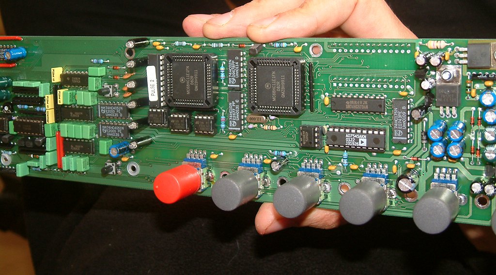
Here you see the two Motorola CPUs and the knobs. This is the digital part of the Pulse doing the Midi, the storage, the front panel and the clock for the oscillators.
Left of the LEDs you see the analog parts that create the analog waveshapes from the digital clock (= pulse, hence the name).
Analog parts
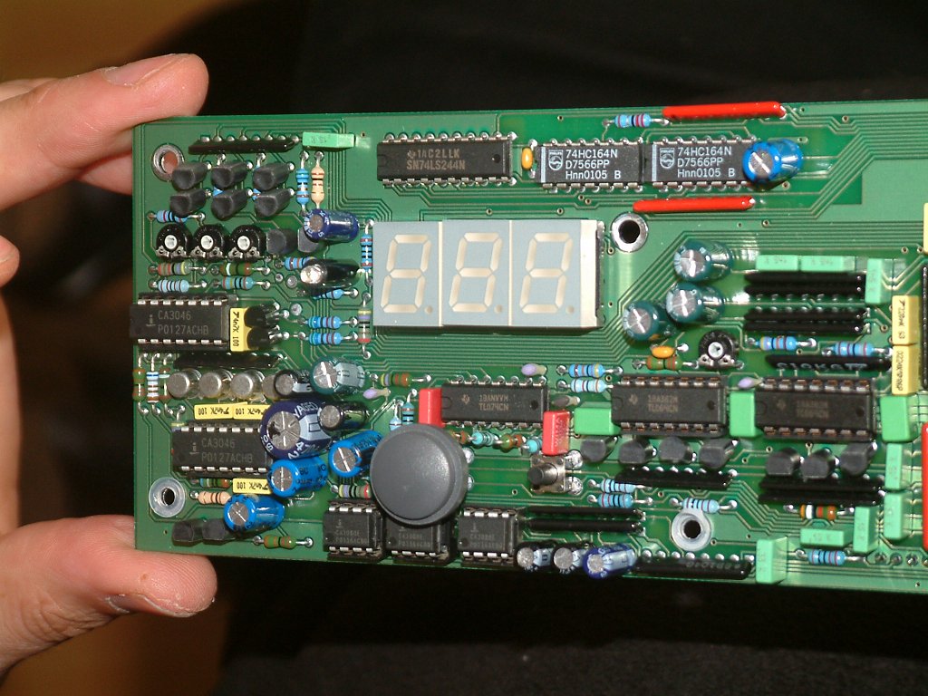
Here you see a detail of the filter left of the display. It uses two CA3046 transistor arrays (5 transistors each) and s4 discrete transistors of the 2N2484 type (the 4 silver ones below the top CA3046). One CA3046 is used to for the differential pair below the Moog ladder. It is also used for the two transistors of the stage above the differential pair. The two top transistors of the ladder are used from the second CA3046 transistor array. The unused transistors of the arrays are all used for other purposes of the filter, but not in the ladder itself.
The OP-amps below the push-button plastic cap are the three VCAs: one for the volume and two for the panning.
The Rev. 3.1
- One Trimmer on the soldering side of the PCB
- Different constructed housing
- No printing on the top of the housing as seen in the first picture
- Nextel paint on the front.
all pictures © Boele "SCD" Gerkes