The Waldorf-User Frequently Asked Questions
The Inside of a Waldorf 4-pole
Beta-Test Version
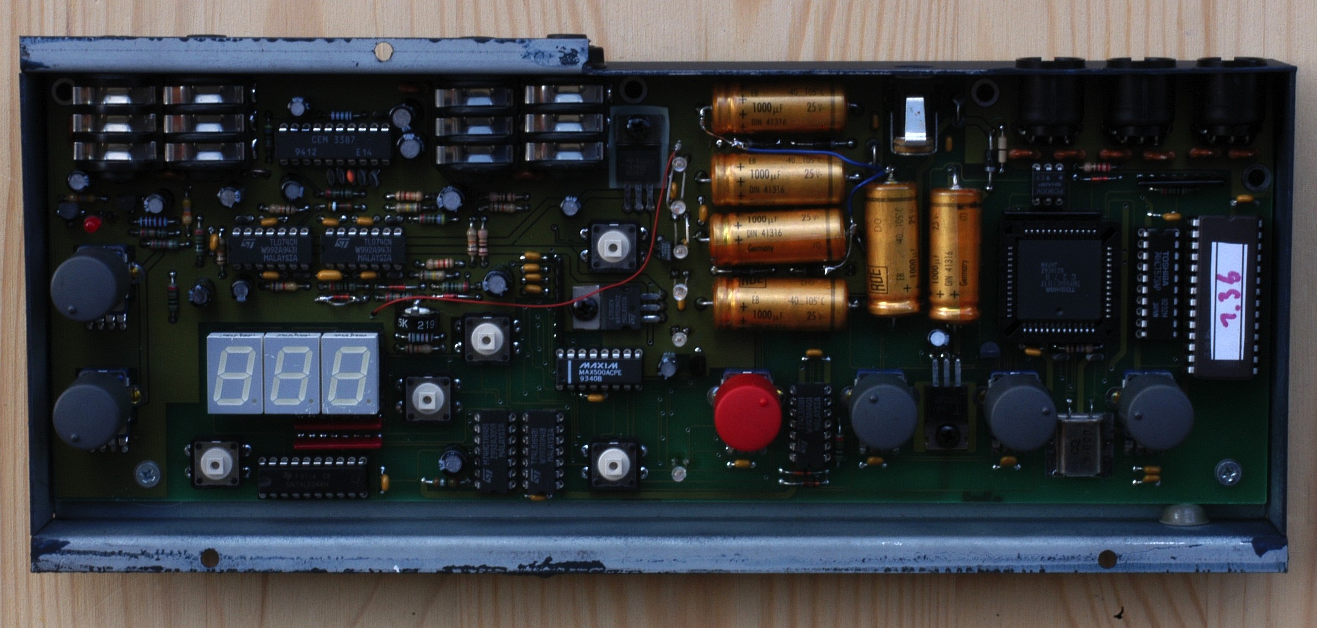
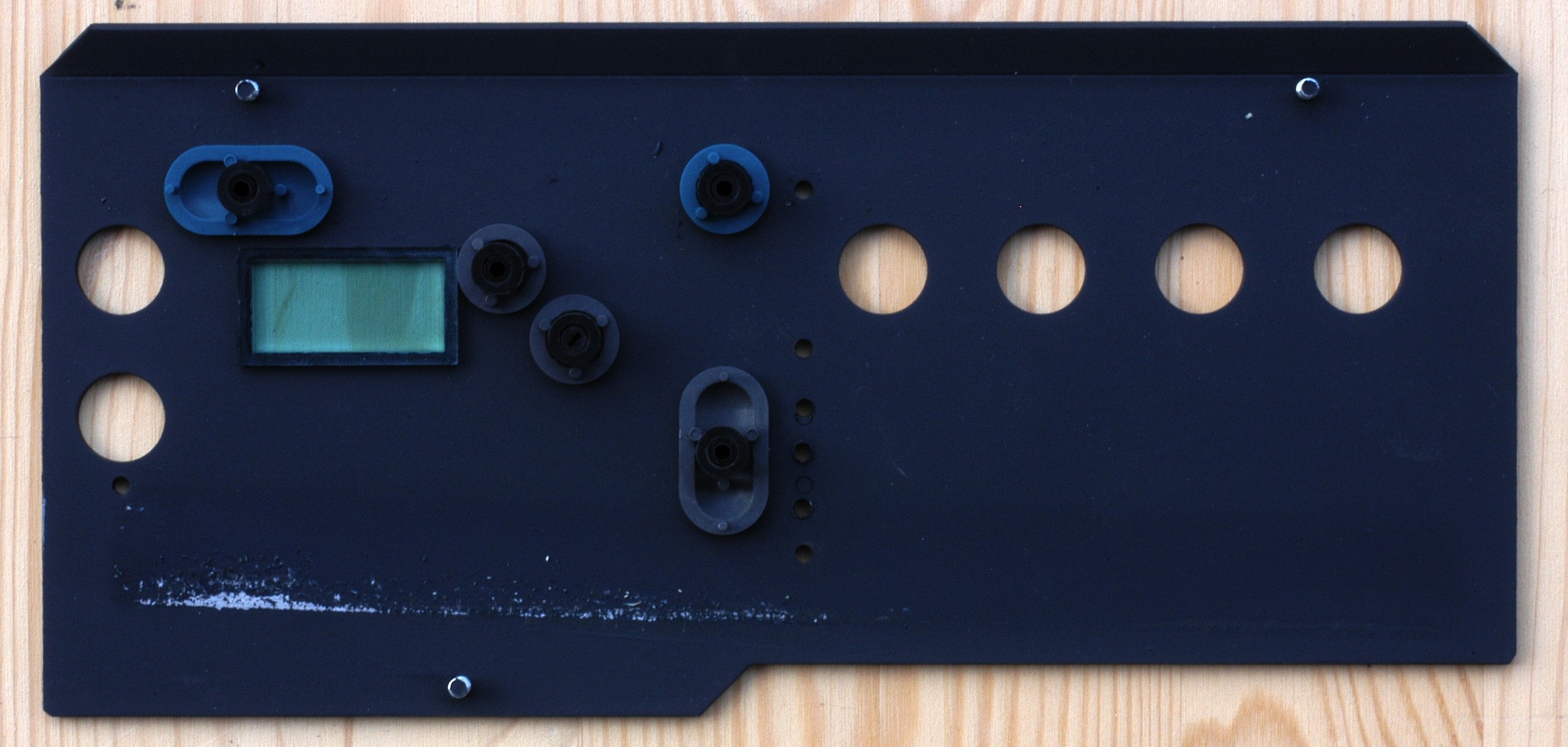
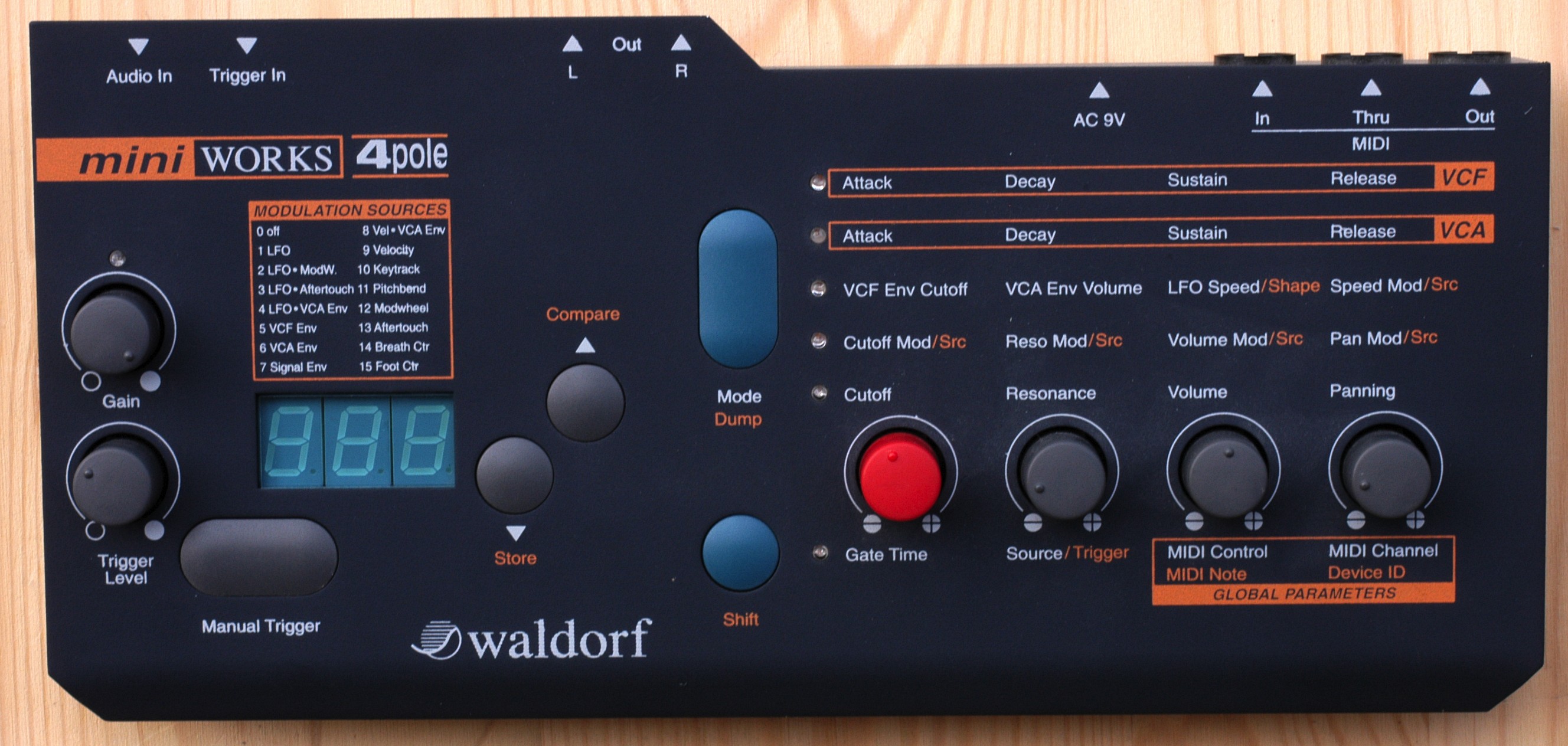
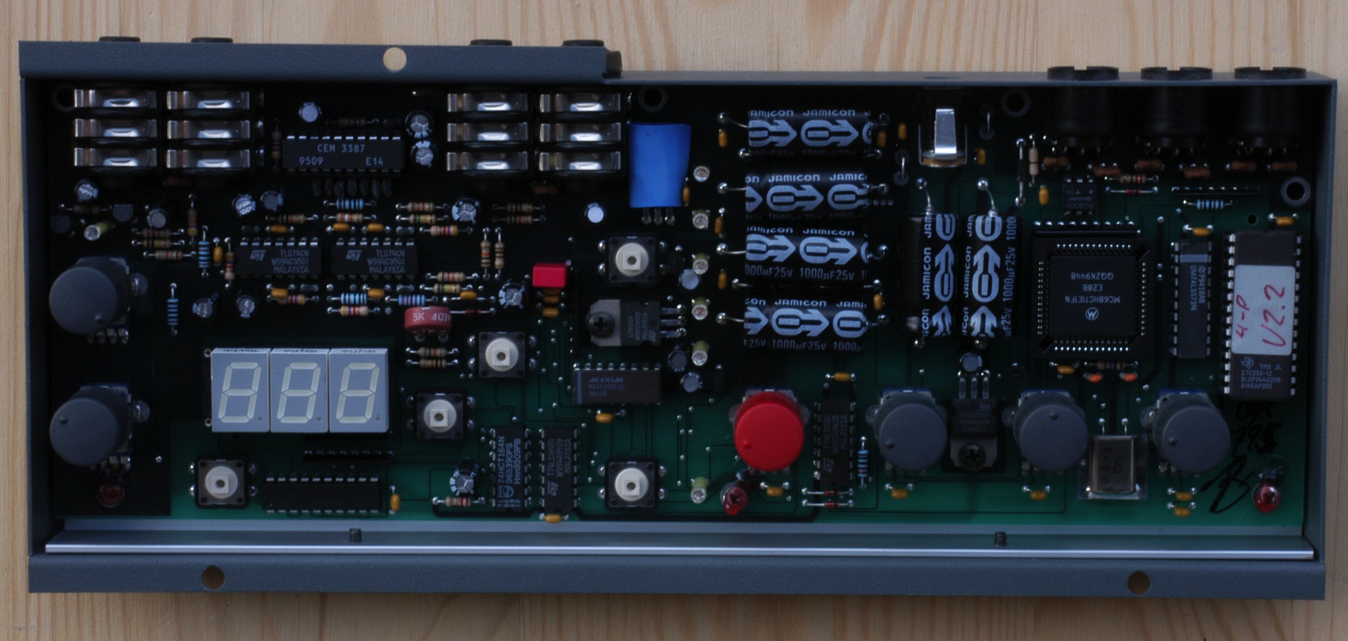
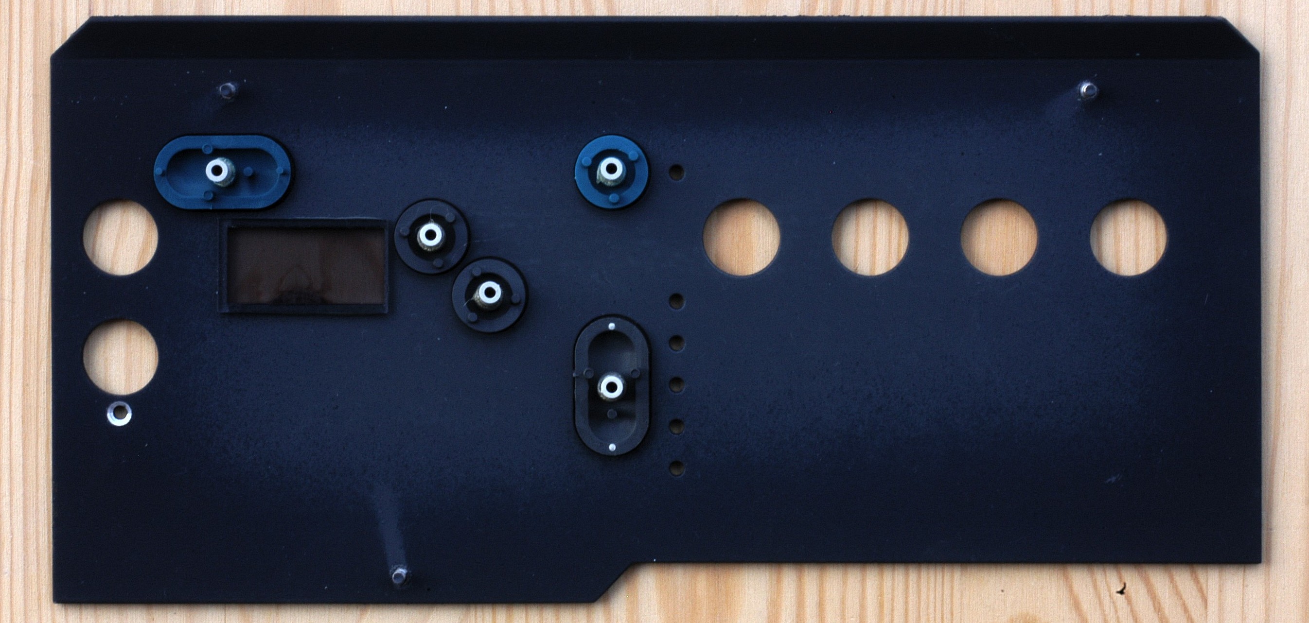
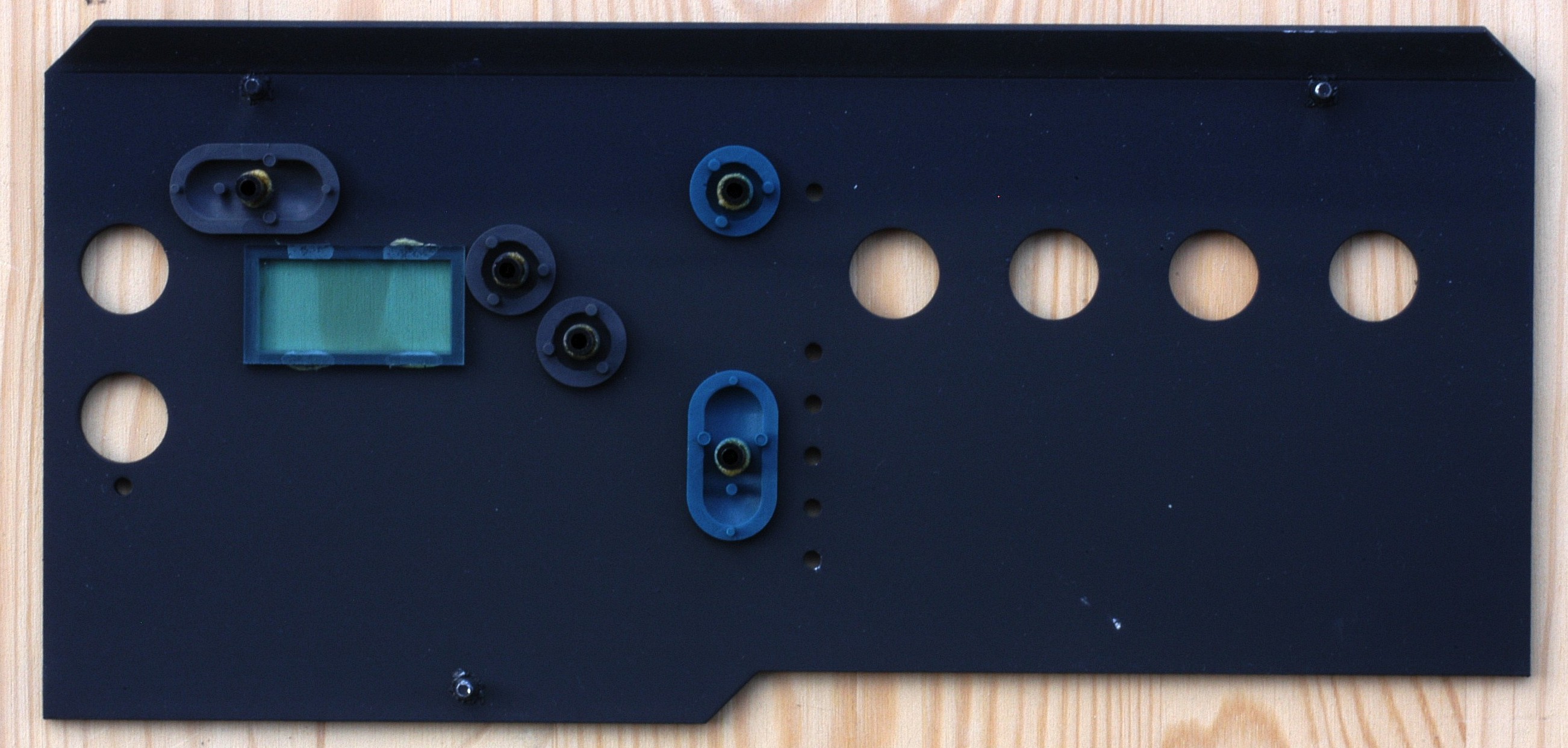
Notice the way to the top LED of the vertical LED line is soldered. There is no trace on the board for it. And the others are bended to fit an additional one. See also the different spread holes for these LEDs on the back of the front plate (pictured below). You can easily spot the Curtis CEM 3387 analog filter chip between the audio sockets.
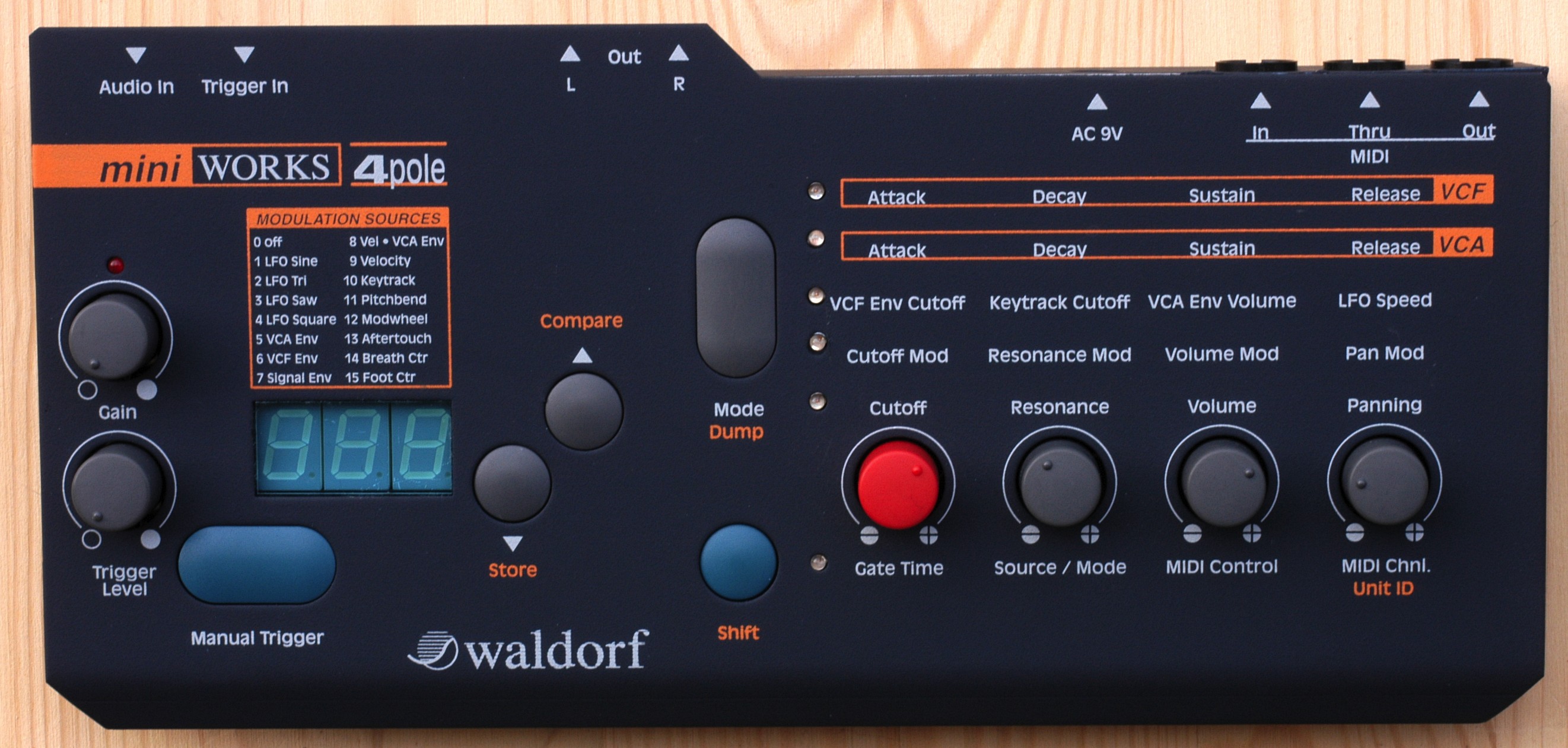
The voltage input is 9V AC. And there is no orange second level label next to the third and forth row of editing level labels.
And the table of modulation sources shows different LFO shapes where the serial version uses LFO level controlled by modwheel, aftertouch or VCA envelope.
Curtis Filter Version
Pulse Filter Version

The voltage in is now 12 V DC. So this voltage label is the best indicator of the version you see, use or buy.
Also notice the changes labels of the audio outputs. No they are not only labeled "L" and "R" in full words, but also added "Stereo" (left socket) and "Mono" (right socket).
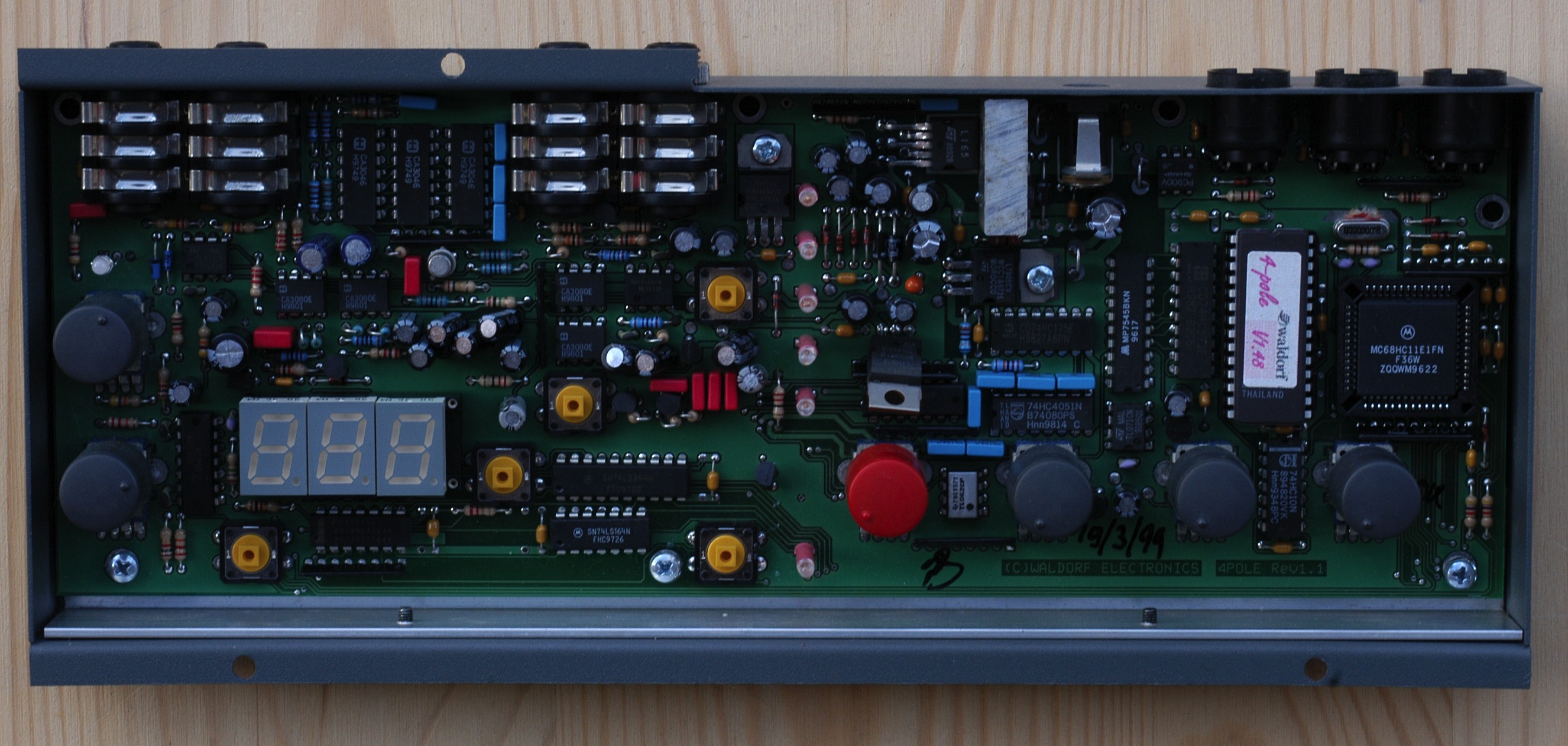
The three transistor array chips CA3046 are used for the transistor ladder of the Moog like Pulse filter here. See also at the inside of the Pulse synth.
The TL074CN "JFET-input operational amplifiers" are now exchanged for CA3080E "2MHz operational transconductance amplifiers".

all pictures © Georg "swissdoc" Müller 2008